|
|
CONTACTS MACHINERY, INC. 25 ch. Schippel Montcalm, QC J0T2V0 PHONE: 866-514-0890 Contact Us About This Machine |
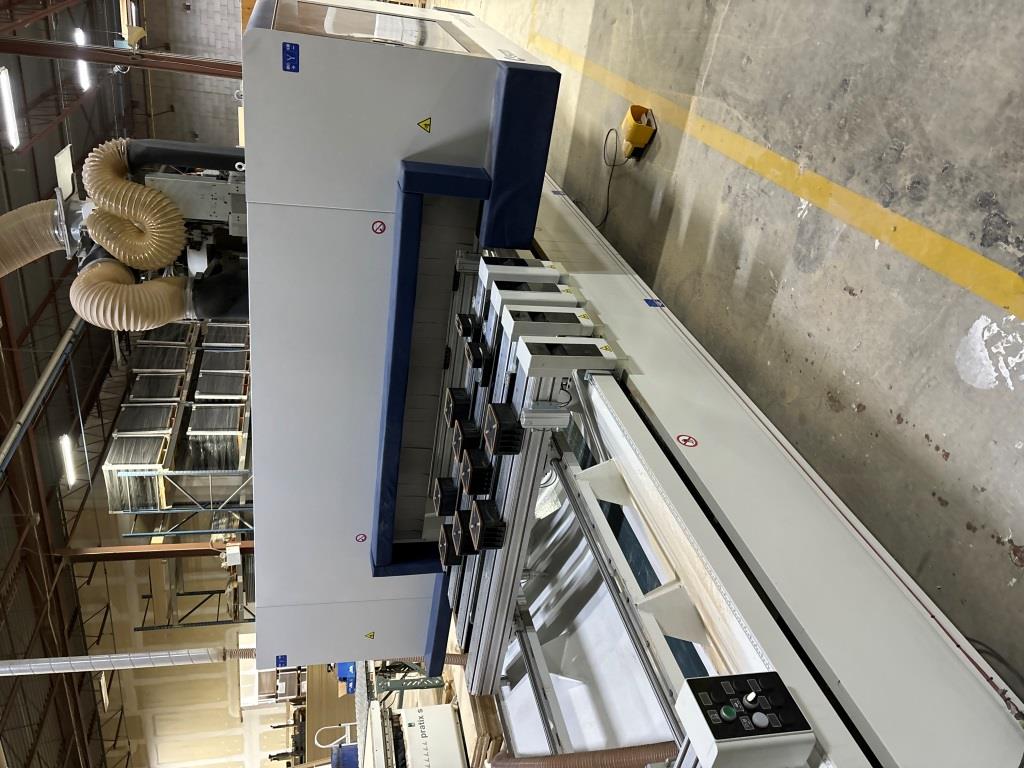
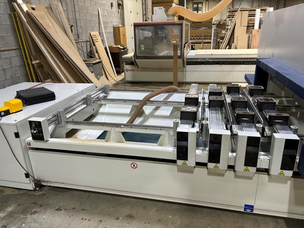
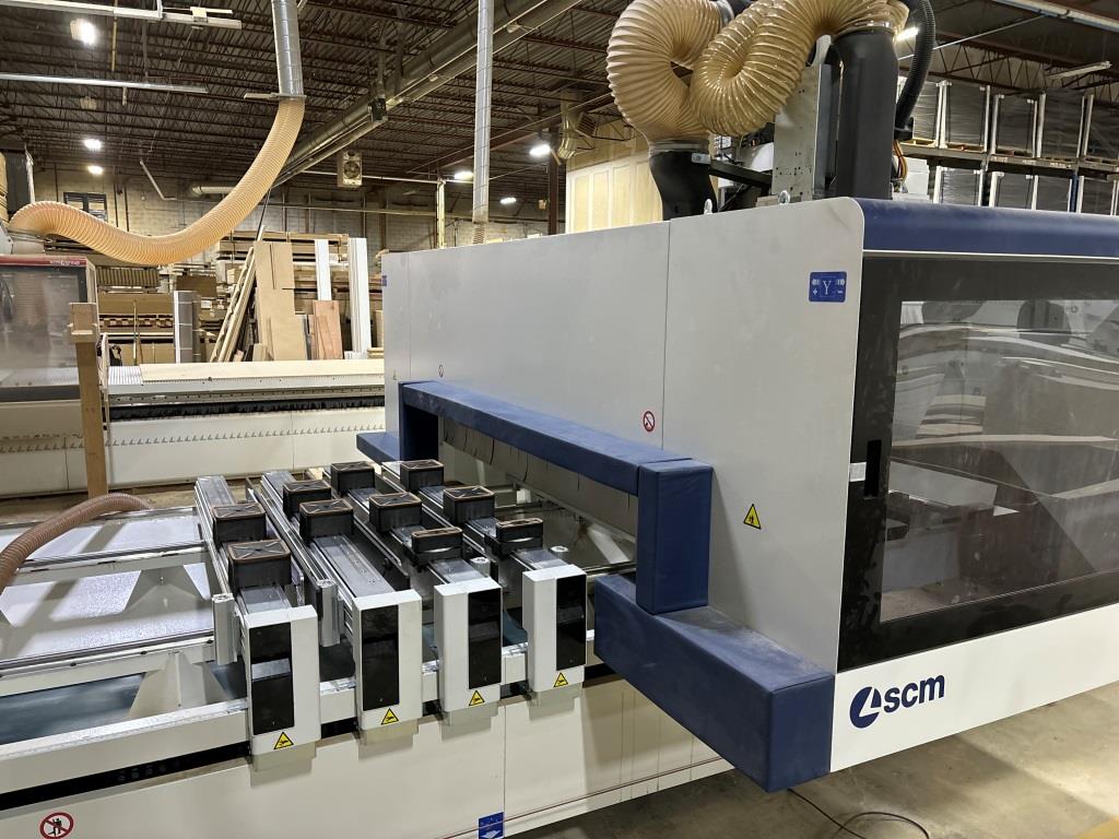
SCM M100 |
||||||||||||||
|
|
|||||||||||||

| Machine Information Sheet | Date: 4/27/2024 |
| Inventory #: | C5211TS |
| Machine Type: | CNC Machining Centers - Pod and Rail |
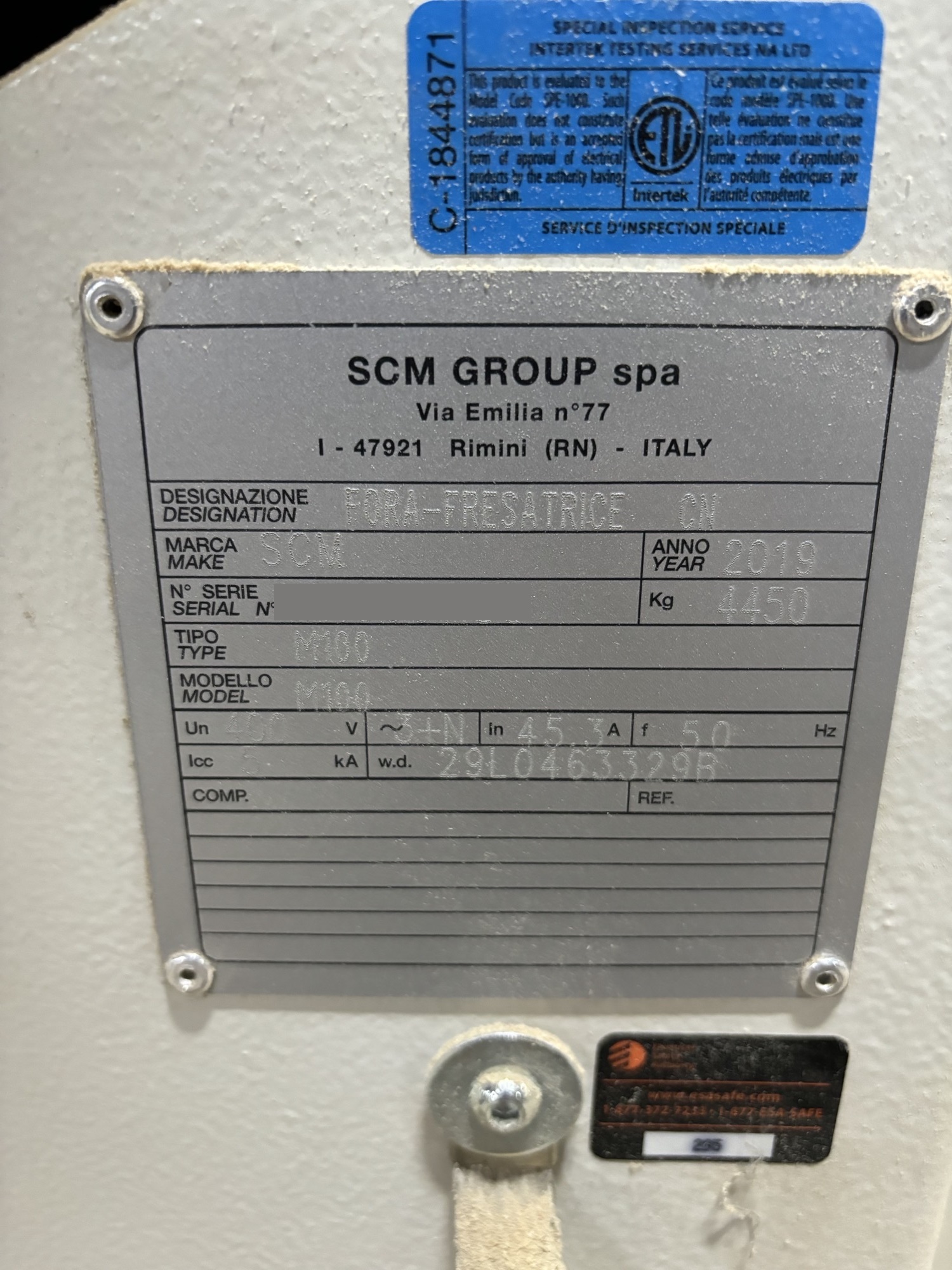
| Manufacturer: | SCM |
| Model: | M100 |
| Year: | 2019 |
| Region: | Central Canada |
| Voltage: |
400/3/50
Can be transformed to required voltage for a nominal fee. Single phase available thru a phase converter. |
| Condition: | Excellent |
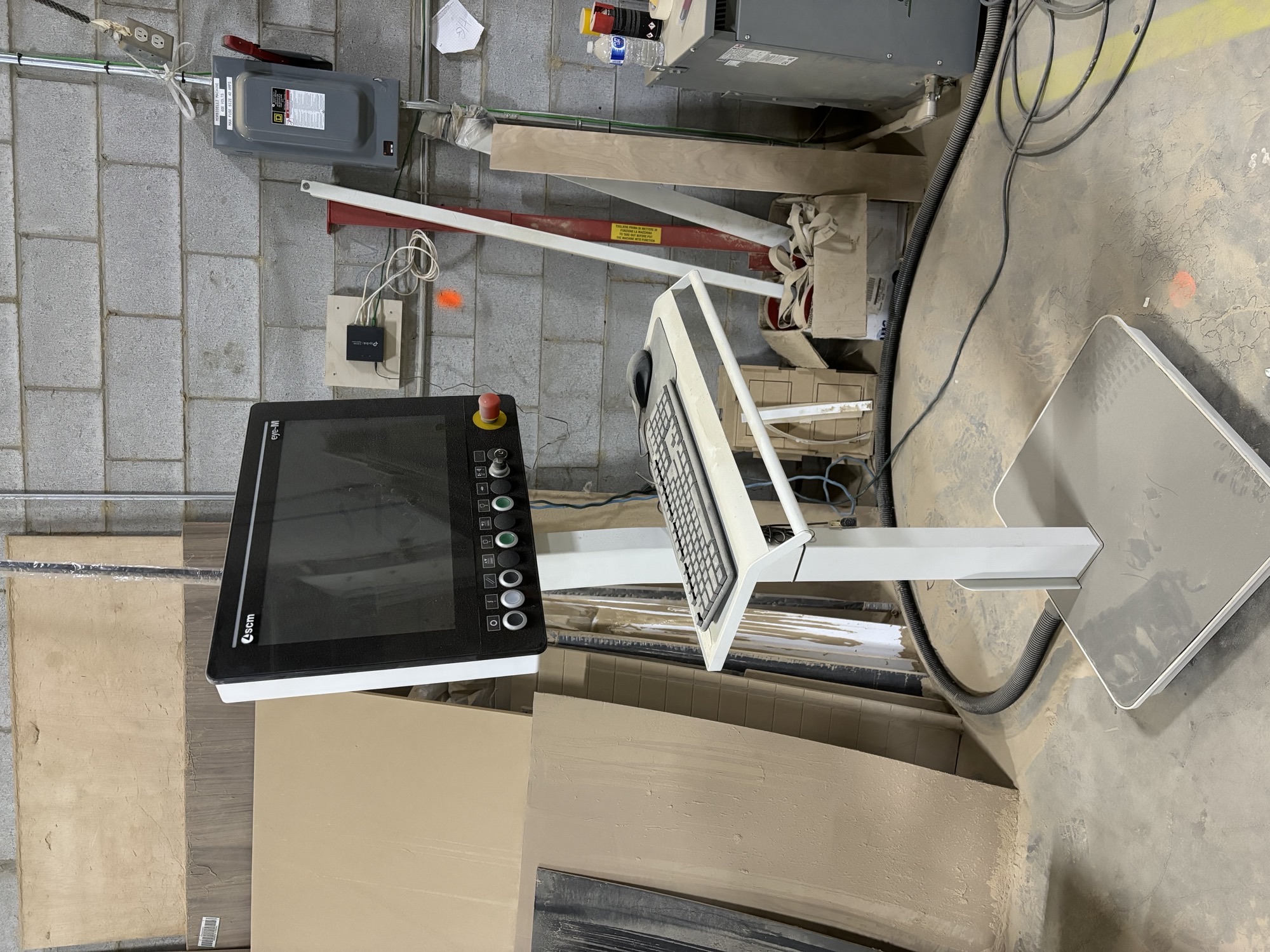
| Machine Capacities: | CNC machine with rich capacity of routing tools and drilling bits to fulfill any requirement in wood and similar materials working industry. ►More performant, with drilling spindles 8.000 rpm and Ro.Ax. technology, the more rigid spindle on the market with more than 1.000 hrs usage without maintenance required ►Fully equipped, excludable and configurable pods on TV FLEX table to set-up properly the working area according any requirement ►Quick and intuitive programming with integrated cad-cam module XILOG MAESTRO ►Best usage easiness, full access to the working table thanks to lowered bottom frame, integrated electrical cabinet and vacuum pump and no fences at all in PRO SPACE configuration Design & construction The bottom supporting structure has been designed to be assembled in a cage� like shape, with all the parts electrowelded one and strongly ribbed one to the other so to reach the best rigidity possible; the particular structure, with a very wide base, grants long lasting stability and precision under all working conditions and doesn`t require the machine being fixed to the ground. The cage-shaped bottom structure provides also a solid support for the mobile unit on top of it: the operating units moving on the cantilever support take advantage of this balanced case thus granting the highest performances in quality and precision. The mobile unit, cage-shaped and ribbed, is anchored to the base through a pattern of sliding supports moving on recirculating balls circuits on prismatic guides: this solution grants the best durability along the entire operating life of the machine. On the cantilever structure the working unit is equipped and moves along Y and Z axis through sliding supports on prismatic guides with recirculating balls circuits. The movement of the mobile unit along the bottom frame (X axis) and the operating units along the mobile unit`s beam (Y axis) is granted through a rack/pinion system designed with helical teeth so to allow tooth-to-tooth higher thrust thus allowing better acceleration and speed along both X and Y axis. Helical teeth, once properly designed are able to reduce also wear on mechanical organs and noise in operating conditions. The vertical Z axis is driven through a recirculating balls screw which ensures perfect balance under dynamic loads and bears very high acceleration and deceleration values. The routing unit is directly installed on the Z-axis slide thus granting the highest finishing quality thanks to a complete absence of vibrations. The displacements along X-Y-Z axes are managed through "brushless" motors driven by static inverters which grant: -Reduced cycle timing thanks to higher accelerations -Better positioning precision through high resolution encoders -No set-up operations once switching on the machine thanks to absolute encoders utilization -No general maintenance operations thanks to the absence of brushes, "brushless" system The management of the axes displacement and generally the devices of the machine is assured by an industrial NC module with digital data transmission carried out through "CAN OPEN BUS" technology, able not only to reach the highest speed in communication intervals but also to be unaffected by external electromagnetical interferences. These factors affect performances in reducing machining times at least by 20% and make possible performing complex operations with the maximum precision. Standard operative equipment Morbidelli is equipped with a series of standard devices able to maximize its general efficiency during daily operations: -"PRO SPACE" safety system, the absence of fences surrounding the machine allows the operator access easily to the working table from any position around the machine with no need to wait for the program ending. The maximum speed of the axes, limited by software to 25 m/min and fulfilling current safety norms, grants the operator working in total safety condition. PRO SPACE system allows Morbidelli take a small sized footprint, thanks also to the exclusive solution in integrating the electrical cabinet and the vacuum pump inside the frame structure, thus giving the ability to install it even in the smallest shops avoiding repositioning on existing equipment with a big save of money and time. -BUMPERS PROTECTION (compliance with CE 2006/42 norm), which surrounds the operating units with a protective cage made up of a metal sheets construction. The front side of the cage is provided with a wide visibility window in ejection-proof material with can be opened during maintenance operations. Sensible soft cushions equip the left and right side of the cage: in case of contact with an obstacle the sensors on the cushions stop immediately any operation on the machine which enters the "emergency" state. The absence of safety devices on the ground floor grants the highest grade of freedom to the operator making him take advantage on the full size of the working table in case of pendulum working. -WIRED REMOTE CONTROL, practical device for the operator to carry out with him the main commands of the machine without being necessary manage them through the main console. Thanks to this device it is possible approaching the machine and command main axes X-Y-Z in a semi automatically modality, enable/ disable drilling spindles, set feeding speed etc. It`s also very effective once checking machining operations while being held or simply simulated so to doublecheck programming before launching an automatic production cycle. -OPTIMIZED DUST EXCTRACTION SYSTEM, the dust hoods, one each operating unit, are conveyed to a single main hood to which connect the general aspiration system. Inside the hood a system of on-off valves, pneumatically managed, opens only the dust extraction circuit relative to the unit currently working so to maximize the cleaning action on the part and reduce air consumption and noisiness. -AIR PRESSURE MULTIPLIER (only on drilling head) provides Ro.Ax spindles with an increased thrust while operating; exceeding 64 kgf on each spindle a full performance on the hardest materials can be run. -AUTOMATIC LUBRICATION CIRCUIT, a NC managed grease pump grants mechanical organs on displacement axes (sliding supports, racks, pinions, recirculating ball screw etc.) be properly lubricated following a given interval of time. Standard maintenance operations granted with this device. An alarm signal will be also provided once the pump runs out of lubricant so to intervene for a full refill. NOTE: Drilling equipment, if configured, respects a different maintenance program due to: -very long intervals in time required (up to 1000 hrs between adjacent interventions) -different grease type -very small lubricant quantities required (see user manual for further details) -VACUUM CIRCUIT, this plant is made up of properly dimensioned organs so to obtain the best performances on flow capacity and vacuum values. The machine can equipped with pump(s) able to grant full retaining actions both on small sized parts and odd shaped ones. -PC-OFFICE WITH MOBILE CONSOLE, to program and manage the machine on the production site through the usage of a Personal Computer, Windows environment based, directly connected with NC module, upgradeable and adaptable to each specific user`s requirement. Any customer can take advantage from this solution in maximizing the effectiveness grade in operating with the CNC machine, even in case of poor familiarity with electronical devices. The PC control unit together with its 19" monitor, QWERTY keyboard and optical mouse are hosted on a practical support, provided with rollers and 6 meters long cables for an easy and quick repositioning. -TELESOLVE EQUIPMENT hardware devices to allow the PC be connected with SCM GROUP Service Dept. through the Internet. Together with the hardware a software packet is installed which allows: -Signals diagnostic recover -HMI visualization -Check and editing on configurations states, parameters and machining programs -Data backup and file transfer -PLC module upgrade -HMI module upgrade NOTE: Internet connection at customer`s charge, Internet cable not included -NETCARD ON PC, dedicated plug to allow the customer connect with a cable the PC office station to the corporate network, thus allowing a real time data transfer to/ from the machine. - XILOG MAESTRO SOFTWARE SUITE USER INTERFACE AND PROGRAMMING Maestro is the software platform equipping all SCM GROUP CNC machines. Maestro is a 3D graphical CAD/CAM suite, developed by SCM GROUP`s software department, which grants an easy and quick programming, basing on the following main functionalities: -Part machining programming -Tool database management -Machine configuration management: operating units, working table, tools store management -Locking devices management (pods, rails, clamps, ... ) -Operative control and machining diagnostic The user interface shows up with an easy-to-use graphics which utilizes the most actual tools in objects representation and follows this layout: -Functions menu, divided in groups, top screen positioned -Geometries drawing, in the middle of the screen -Geometries and machining operations properties, right side positioned, with drop down menu -List of operations, left side positioned, tree structured CAD functions cover a wide range of choices through a sketching environment which includes basic geometries: -point -line -arch -circle -ellipse -polyline -polygon -slot -text On these basic geometries additional operations can be performed such as chamfers, fillets joints. Aided drawing functions are also available, same than any CAD software: -osnap -cut -copy -move -opposite -mirror -offset -rotate -reversed orientation on geometry -editable starting point on geometry -distance measuring Xilog Maestro allows the operator create his own macros and sub-programs, to be added to the preconfigured apps (drilling patterns, routing patterns, geometries etc.) which represent the most common construction schemes on furniture. Parametric programming is included: parameters can be assigned on main machining program and/or sub-programs and/or macros. Tools management A dedicated application inside Maestro, named "Tool Manager", takes care about it: this environment shows tools grouped in categories and graphically represented to grant an immediate and intuitive access to the operator. Each tool has an identification tag so to be immediately recovered once the tool selection is required in programming mode. Maestro APPS A library of programming functions fully available and easy to use, developed by SCM GROUP and specific to machine furniture elements, doors, stairs, windows etc. A simple "click" allows the operator get full access to SCM GROUP`s technological know-how. Through Maestro APPS you have the ability to choose the type of machining required and drag it on the geometries you wish it to be applied on. Working table management Working table set-up definition is a totally graphic operation. The operator has the ability to: -visualize the 3D model of the working table on his machine -through a "drag and drop" operation equip the working table with the necessary locking devices -drag rails/ pods/ clamps to the required position under the part to be machined -use parameters to define position on locking devices, a real effective function for those who produce in "batch 1" regime -insert a repositioning operation on rails/pods/clamps inside the same program -check eventual collisions between machining devices and locking ones -check aspect on finished parts -ask the software to define automatically the best positioning on locking devices (in case of TV FLEXMATIC table locking devices will set-up automatically on the working table) Cycle time evaluation Maestro is equipped with a preconfigured module which - according to the programmed operations, tool changes involved, tool paths defined etc. - is able to provide a numerical value of the timing required to execute a single program. This function is strongly effective in: -evaluating the productivity of your CNC machine before starting the production of a batch of parts -comparing different versions of the same program so to optimize and reduce at the best the cycle time -estimating the cost of a supply in terms of machining hours NOTE: This software function provides only a simulation, the data obtained from a real processing cycle may vary in a value range by +I - 10% Data import Xilog Maestro allows external files to be imported: -DXF files import a DXF file is imported, the operator may edit geometries through the drawing tools on Maestro and/ or directly apply the required machining operations, exactly as they were being created through Maestro -PGM files import PGM programs - created through previous programming suite (Xilog Plus) or external software sources - can be imported; Maestro reads and converts them into PGMX format (standard Maestro format) so to be then completed with working table set-up module, cycle time evaluation module etc. MSL Connector MSL Connector (Maestro Scripting Language) is the software module developed by SCM GROUP so to connect directly its own CNC machines with the main softwares on the market. The data coming from external sources softwares are imported into the machine which - basing on the parts dimensions and the machining operations to be executed - manages the process strategies optimizing the position of the locking devices and the tool paths. Machine Management Panel PanelMac is the applicative software module which is used as Human-Machine Interface on any CNC machine by SCM GROUP. Its basic feature is the ability to communicate with NC module and use this connection to manage the machine itself. Main functionalities on PanelMac: -machine set-up -semi automical commands management -manual positioning of mechanical organs -part program execution (PGMX)* -tools management * The part program is not being entirely communicated to the NC module before execution; the so called "gothrough mode" is used and it consists in splitting and sending single parts of the same program to the NC module. This type of communication allows a program to start immediately and it`s pretty useful in case of very complex programs which involve hundreds or thousands of instruction lines. While the machine is running a program in parallel and uninterruptly the NC module is receiving data from PanelMac till the full completion of the program. Program Restore once Interrupted (PRI) PRI procedure allows a program to restart from the point of interruption due to the occurrence of an "emergency" state. This procedure foresees these actions: -a part program being executed in AUTOMATIC MODE gets interrupted due to an "emergency" fault -the operator intervenes manually to solve the problem causing the "emergency" state -once the fault is solved, the operator activates PRI procedure through PanelMac (pushbutton) and commands again the part program execution -PanelMac, being in PRI mode, checks the interruption point and recovers the program starting from the beginning of the operation the machine was running at the moment of the interruption (not exactly from the point of interruption); therefore part of the operation will be executed again and then the program will run till the very end. NOTE: This procedure works only if the AUTOMATIC EXECUTION MODE of the part program won`t be deactivated once PRI is required Software protection Xilog Maestro is protected against unauthorized copy through hardware USB key. Any CNC machine comes standardly equipped with n.2 USB keys so to allow the software suite be used both on the machine`s PC console and any other external PC (minimum hardware requirements to be granted for a proper use) at the same time. The additional hardware key is not associated to a single user or PC so the customer can install Maestro Suite on different PC consoles and use the one more suitable in any moment simply carrying the hardware key. -WORKING TABLE The working table has been designed for a practical and safe use of any device equipping it and, most of all, for a quick and easy configuration during daily operations. -Vacuum pods fully excludable from the table, each pod is rigidly locked to the rail through a pair of safety locking systems: mechanical one, thanks to bottom profile of the pod which gets stuck onto the top surface of the rail and pneumatical one, thanks to a mobile profile on the side of the rail which runs along its length and enlarges thus getting stuck inside the base of the pod. During parts loading/unloading operations the pods stay locked thus preventing any accidental movements. This technology turns into a working table free from vacuum tubes, plugs or connectors and provides the ability to lock even small sized parts simply pairing pods and/or rails to the minimum distance possible. The vacuum pods, properly designed in different layouts available on price list, allow them to be positioned back-to-back so to create the right set-up according to the most various shapes to be machined. The supporting rails, rectified and extruded aluminum made with wide support base, slide along the X axis on hardened round guides and are equipped with a rigid and safe locking/unlocking system consisting in two pneumatical brakes (one on the front side of the rail, the other on the rear side). The use of this technology grants the security of an easy and ergonomic handling and precise positioning. The vacuum circuit which holds the parts to be machined is canalized inside and through the rail itself, providing negative pressure to the pods through a row of steel spheres along the rail which are activated through mechanical pressure. Each rail is equipped with two referencing pins, pneumatically managed and integrated inside the aluminum structure: -the first pin is located on the rear side of the rail to allow the locking and machining on big sized parts -the second pin is located in an intermediate position on the rail to allow locking and positioning on middle and small sized parts On the left and right sides of the working table are located four other pins (two each side) to allow side referencing be possible thus granting the machining of "left" and "right" parts as well as pendulum working with an increase in productivity. All the pins are managed automatically according to the machining program. The enabling of vacuum circuit for parts holding down takes place through a pedal switch: in this way the operator is free to load/unload parts with both hands in a really ergonomical way. As an option, the rails can be equipped with side supports able to raise up and down pneumatically on which the operator can place the part to be machined and push it easily against referencing pins. These supports work also to detach parts from vacuum pods once the process has been completed. The internal area of the bottom frame is properly shaped as a "fall-in" geometry so to convey scraps and dust falling from the working table towards the central area where a motorized belt conveyor (optional) carries them outside the frame itself (conveyor orientation right-to-left). Production code: Ml00 -ESECUZIONE USA/CANADA -MORBIDELLI Ml00 3710X1620 Z180 -VOLT 380 -FREQUENCY 60 HZ -PRO-SPACE SAFETY SYSTEM. It allows to install the machine without peripheral protections, maintaining the overall dimensions for the installation reduced to the minimum. Safety protections directly positioned on the upright structure; maximum X axis speed = 25 m/min -AIR CONDITIONING ON ELECTRICAL CABINET. It maintains the temperature inside the electrical cabinet within the values of a correct machine use. This option is advisable in environment with temperatures over -"TECPAD WIRED" REMOTE CONTROL WITH 7" TOUCH-SCREEN COLOUR DISPLAY Mobile control panel which allows the machine control for all programs execution, the manual control of axes, the errors management and the graphic positioning of rails and pods. Mobile control panel able to fulfill multiple operations on the machine. It is equipped with: -n.2 override potentiometers to manage speed on operative devices (i.e. drilling bits rotation, main axes speed etc.) -n.19 buttons on keypad: 6 keys are command keys, useful for a direct machine control while the remaining 13 keys are function keys, useful for navigating and operating through the panels of the software application (i.e. managing the positioning of pods and rails during set-up phase). The letter or the symbol printed on the keys reminds the function -n. l red push-button to activate emergency state -a rubber protection against accidental damages -a left side handle to give the operator the ability to act easily on commands with the right hand free -back side magnets to allow the operator an easy and immediate placement on the metallic parts of the machine so to have both hands free -TRB14 LINEAR TOOL CHANGER (Y=1620 VERSIONS). Linear tool changer located on the right side of the bottom frame of the machine and able to host tools and/or angular heads (please refer to admitted dimensional limits reported on layout chapter). This device is build with a steel frame so to grant the best rigidity possible in case the heaviest tools would be equipped on it. The tool-holders housings are covered in plastics and provided with an alumimium support so to provide an ideal connection between rigidity and resiliency on the tool-holder support during tools loading/unloading operations. Switching tools function between this tool changer and the others equipped on the machine is also available to reduce cycle time during machining operations and avoid idle times to equip tools on the on-board tool changers. Technical data -max. tools allowed: 14 -max. tool diameter: 300mm (3 axis machine), 350mm (5 axis machine) -distance between positions: 115mm -max. tool weight: 8kg -max. total weight: N.A. NOTE: Tool-holders and clamps not supplied -FAST14 LINEAR TOOL CHANGER. FAST 14 tool change grants the best performances in terms of time during changing operations given the small distances from the router and the tool to be equipped and a dedicates software optimization managing changing sequence. It is located inside the protective cage on the mobile unit and able to host tools and/ or angular heads (please refer to admitted dimensional limits reported on layout chapter). This device is build with a steel frame so to grant the best rigidity possible in case the heaviest tools would be equipped on it. The tool-holders housings are covered in plastics and provided with an alumimium support so to provide an ideal connection between rigidity and resiliency on the tool-holder support during tools loading/unloading operations. The rake and the tool-holders are properly protected against dust through a roof on its top. Technical data -max. tools allowed: 14 -max. tool diameter: 225mm (tool blade), 180mm (circular tools on angular heads) -distance between positions: 7 positions distance 110mm, 7 positions distance 130mm -max. tool weight: 8kg -max. total weight: N.A. NOTE: Tool-holders and clamps not supplied, not compatible with dowelling unit code 63.04.84, mandatory TRitool change -AIR BLOWER ON ELECTROSPINDLE. It allows to convey a cooling air blow on the tool, during the machining. -NO. 1 VACUUM PUMP 250/300 M3/H 50/60 HZ.CENTRALIZED OPTIMIZED AIR COVEYOR ON REAR HEAD Air conveyor which groups all the machine exhaust outlets and allows to connect it to the general dust collector system through one main exhaust outlet. Inside the main dust collector are fitted pneumatic cylinders that control automatically the opening/ closing of each exhaust outlet when the operating unit is switched on/off -F31LTC DRILLING UNIT. The drilling unit is equipped with new roto-axial technology Ro.Ax. Entirely developed by SCM GROUP, this project grants: -improving cutting quality, thanks to the increased rigidity of the spindle (enlarged diameter of the rotating shaft and direct connection, no mechanical interfaces involved, between drilling bit and the shaft itself thanks to Weldon attachment type) -increasing production rate thanks to a maximum rotation regime up to 8.000 rpm (with optional inverter) which allows a higher penetration speed into the material -reducing maintenance interventions, up to 1.000 hours with lubricating mechanical organs on the unit F31LTC drilling unit includes: -bits attachment on vertical and horizontal spindles 10mm, WELDON type (max. length of the bits 70mm) -32mm step between adjacent spindles -n�21 vertical spindles with independent pneumatical selection -n�5 horizontal drilling units with double outlet (one bit each side), 3 along X direction and 2 along Y direction -rotation regime on drilling bits 4.500 (2.500 to 8.000 rpm with optional inverter) -n�l integrated blade along X direction (max. diameter 125mm, thickness 2,2 to 6mm) -rotation regime on integrated blade 5.500 (3.500 to 10.000 rpm with optional inverter) -preset for hinges unit (unit not supplied) -driving motor power rate up to 3,9 kW (5,3 hp) - [2,2 kW (3 hp) with 50 hz frequency] -60mm on-off pneumatical stroke on vertical spindles and blade -75 mm on-off pneumatical stroke on horizontal spindles -locking system on drilling bit "quarterlock" type which allows assembling/ disassembling tools through the use of single M8 screw and 90� rotation on the wrench -compressed air circuit with high pressure to grant more than 64 kgf thrust on each drilling spindle so to perform operations on the most resistant materials -DRILLING UNIT FOR HINGES HOUSING 45/9,5 OFFSET - REAR SIDE Dedicated device to be equipped on F29LTC and F31LTC units, integrated on them aside the grooving blade. Provided with independent pneumatical enabling it allows to carry out the three holes for the housing of the hinge in a single shot. -maximum tool length= 57,5mm -horizontal and vertical bit attachment 0 10mm, WELDON type -offset between external bits = 45mm -offset between the external bits and the internal one 9,5mm The device is oriented so to allow the drilling of hinge housing having it referred to the rear side of the panel. -EXHAUST OUTLET FOR DRILLING HEAD. Positioned around whole perimeter. -DRILLING UNIT MANAGED BY INVERTER. It allows the rotating speed programming up to 8000 rpm maximum for the drilling bits and 10000 rpm for the saw blade. The inverter managing the tools speed rotation on the router is connected also the driving motor on the drilling unit so to allow adjusting the speed rotation on bits up to 8.000 rpm and up to 10.000 rpm on the integrated saw blade. NOT: While executing a machining program, switching from routing to drilling operation, as well as the contrary, requires waiting for the router (or driving motor) stop before enabling driving motor (or router). -DEVICE TO INCREASE THE DRILLING PRESSURE ALONG Z AXIS -VERTICAL ROUTER 9.5KW - 13HP In includes: -HSK F 63 quick release tool-holder. -1500 - 24000 rpm spindle speed -(S1/S6) 8/9,5 kW (11/13 Hp) constant motor power from 12000 to 18000 rpm -right and left rotation -static inverter for continuous speed and rapid shutdown of rotation -exhaust hood around whole perimeter Main routing unit equipped on a cast aluminum sliding support NC managed. Technical data: -HSK 63F attachment with double referencing surface to ensure a rigid connection between the tool-holder and the electrospindle itself -electronic rotation control on speed, from 1.500 to 24.000 rpm through static inverter, quick-stop function on rotation standardly equipped -constant power rate (S1/S6) 8/9,5 kW (11/ 13 hp) from 12.000 to 18.000 rpm -programmable left and right rotation -inner air blowing system to guarantee a proper fitting with tool-holder -cooling system through forced air ventilation circuit and coaxial fan -ceramic bearings as support on the main shaft -compressed air circuit inside the router cage as prevention against dust pollution -perimetrical dust aspiration hood with ON-OFF pneumatical selection and 3-positions manual adjustment NOTE: Tool-holders and clamps not supplied -EXHAUST OUTLET FOR 3-4 AXIS ELECTROSPINDLE -PRESET FOR HITECO AGGREGATES WITH 1 PNEUMATICAL OUTLET. Ring shaped device directly assembled on the main router to allow routing/drilling aggregates with antirotational pin be properly equipped (HITECO attachment). It is provided with a pneumatical outlet for angular heads in need of an air flow (i.e. floating aggregates, horizontal routing aggregates etc.). -N.8 RAILS "TV FLEX" - 1600 Worktable with 1600mm rails and vacuum pods (optional to be added) that grants the maximum grade of easiness in setting up and usage. The ability to configure pods with no constraints both on the position along the rail and the quantity on the single rail make the set-up -always possible with the best configuration independently from the the machining program. The worktable is equipped with: -8 rails with extruded aluminum structure, manually mobile along X axis, sliding through preloaded recirculating balls supports round tempered and grinded guides, located at the ends of the rails to grant full stability in any working condition -automatic locking/unlocking system on each rail: it works through pneumatical cylinders on the round guides through a push-button in ergonomical position to grant maximum easiness once moving the rails -8 referencing pins with 100mm stroke, aluminum made, automatically and pneumatically managed, integrated inside the rail (one pin per rail) and rear positioned to align panels along Y direction -8 referencing pins with 100mm stroke, aluminum made, automatically and pneumatically managed, integrated inside the rail (one pin per rail) in intermediate position to align smaller sized panels along Y direction -4 side referencing pins aluminum made, automatically and pneumatically managed, positioned two on the left and two on the right side of the working table on dedicated fixed supports, to align panels along X direction; all the pins are automatically managed according to the machining program -row of steel spheres along each rail; the spheres have the ability to float on helicoidal springs to allow the automatic enabling/ disabling of the integrated vacuum circuit -mechanical locking on the pods through a movable edge able to lock in a single step all the pods equipped on the rail Each referencing pin is equipped with a female thread on top of it to allow the equipment of optional devices (i.e. references for projecting edges, narrow parts clamps, extension devices etc.). All the rails have the ability to travel along the entire length of the working table in order to grant best flexibility in case of single field machining program. Working areas: A (I offset) and D (L offset). -The working table is equipped with a pneumatical circuit, referencing pins and software to allow locking and machining on maximum two panels on four available working areas: -I Area offset 650 mm respect to A area -L Area offset 650 mm respect to D area -SHAVING EXPULSION MAT FOR X=3710MM Belt conveyor positioned on the bottom frame, underneath the working table and dedicated to convey chips, scraps, dust etc. outside the working area. The optimized width of the belt allows an efficient evacuation of waste materials thus granting an uncomparable cleanliness on working table. NOTE: With PRO-SPEED safety system installed, an additional sliding box is added at the end of the belt conveyor to grant an easy evacuation of chips and scraps outside of the safety fences. -TOOL LENGTH DETECTION DEVICE. Electromechanical device located on the side of the bottom frame and able to detect the tool length through a dedicated software cycle. The length just evaluated will be sent to the Numerical Control which update automatically the tool database in sight of any successive machining program (it is strongly suggested involving parametric programming to take full advantage from this practical function). -N.6 LIFTING DEVICES H=75 - 1600 Devices dedicated to the support of the panel during loading and referencing operations towards pins and make it easy detaching the panel from the vacuum pod at the end of the machining process. They have been realized in phenolic material, positioned on the side of the supporting rails and equipped with vertical displacement pneumatically managed ON /OFF. The material utilized has been conceived so to grant the lowest friction possible on the panel and even heavy parts can be aligned very easily while no scratches will occur during detaching operations. The lifting devices are equally distributed on working areas A and D, 3 on each area, and a single device is able to carry about 40 kg in weight. -FRONT REFERENCING PINS H=75 FOR 8 RAILS These devices are the ideal solution to refer panels on their front side if necessary or to align quickly small sized parts without involving integrated intermediate pins. Group of 10 referencing pins, aluminum made and 100mm stroke, positioned as follows: -on the side on each rail, frontally positioned towards the operator, in total 8 pins -one on the left side of the working area and one on the right side on dedicated fixed supports The pins are hosted on a shaped profile on the rail which allows them sliding and, if necessary, the operator can unlock and move them from the predefined position thus creating a new reference position customized to proper machining requirements. Each referencing pin is equipped with a female thread on top of it to allow the equipment of optional devices (i.e. references for projecting edges, narrow parts clamps, extension devices etc.). With these pins, the machine working table is configured with the additional working areas: E (left side, A and I alternative area) and H (right side, D and L alternative area). -16 FIXED POD 145X145 H=75 MM -16 ROTATING POD 145X55 H=75 MM -CABLES LENGTH OF THE MOBILE CONTROL PANEL 6,5 METERS |
| Sales Price: | CALL FOR PRICING |
| Contacts WW Machinery, Inc. sells pre-owned machinery on a first come, first served basis. Pre-owned machinery is not covered under any warranty or Government requirements. It is purchased "as-is - where-is, with all faults." Descriptions and specifications are to the best of our knowledge (some information is communicated via third party sources). It is strongly recommended that the machinery be inspected prior to purchasing to confirm the condition and specification. Additional charges such as crating and loading may apply. |