|
|
CONTACTS MACHINERY, INC. 25 ch. Schippel Montcalm, QC J0T2V0 PHONE: 866-514-0890 Contact Us About This Machine |
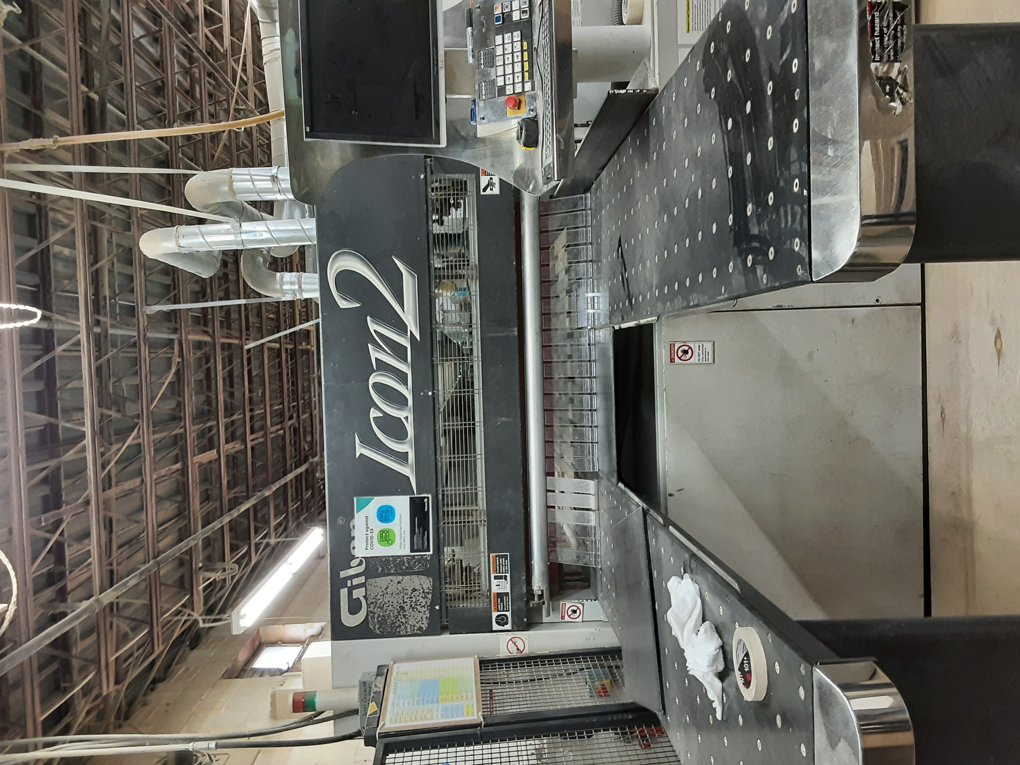
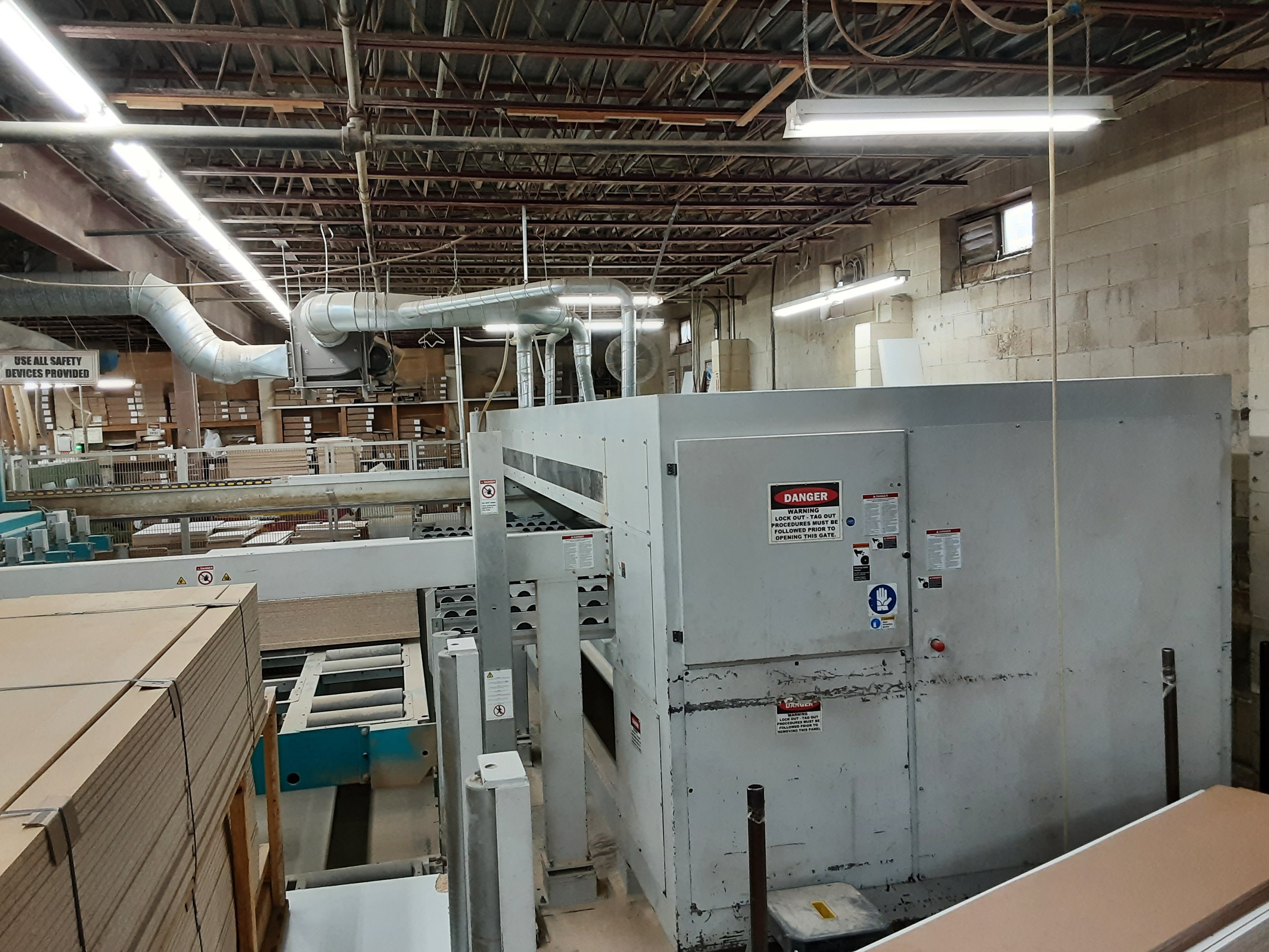
Giben ICON2 h105 |
||||||||||||||
|
|
|||||||||||||

| Machine Information Sheet | Date: 4/27/2024 |
| Inventory #: | C5087TS |
| Machine Type: | Saws - Panel Beam |
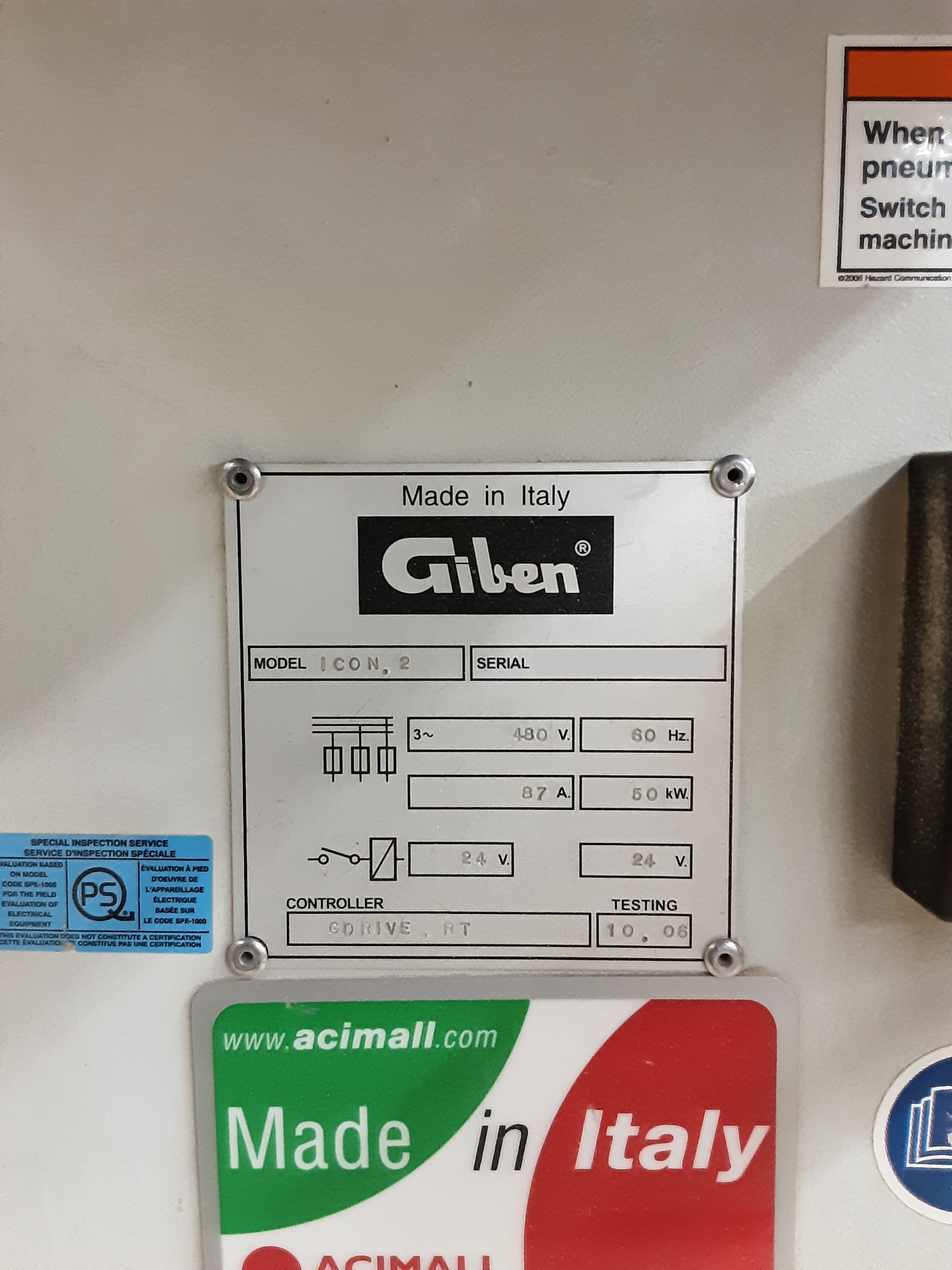
| Manufacturer: | Giben |
| Model: | ICON2 h105 |
| Year: | 2006 |
| Region: | Central Canada |
| Voltage: |
480/1/60
Can be transformed to required voltage for a nominal fee. Single phase available thru a phase converter. |
| Condition: | |
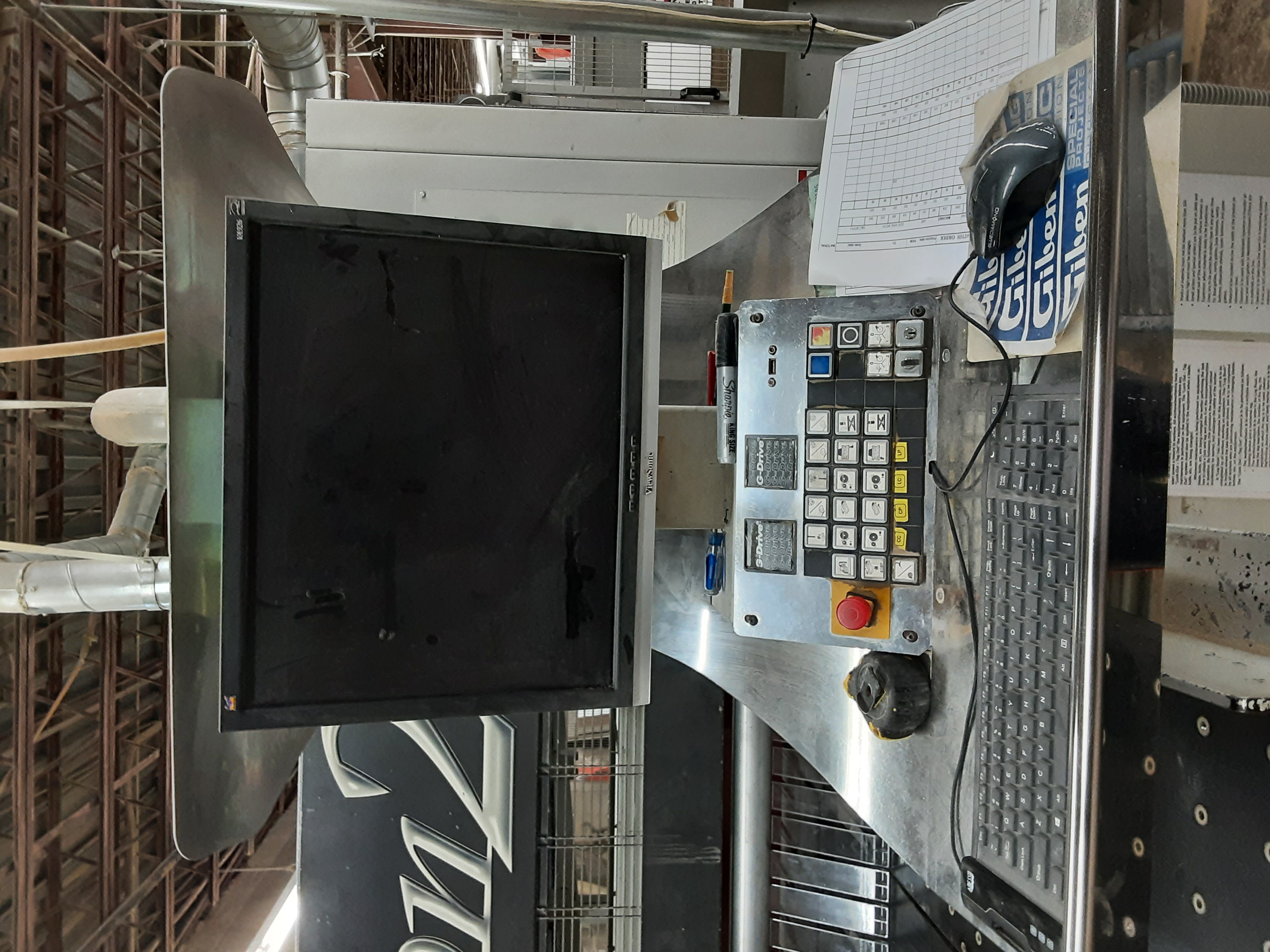
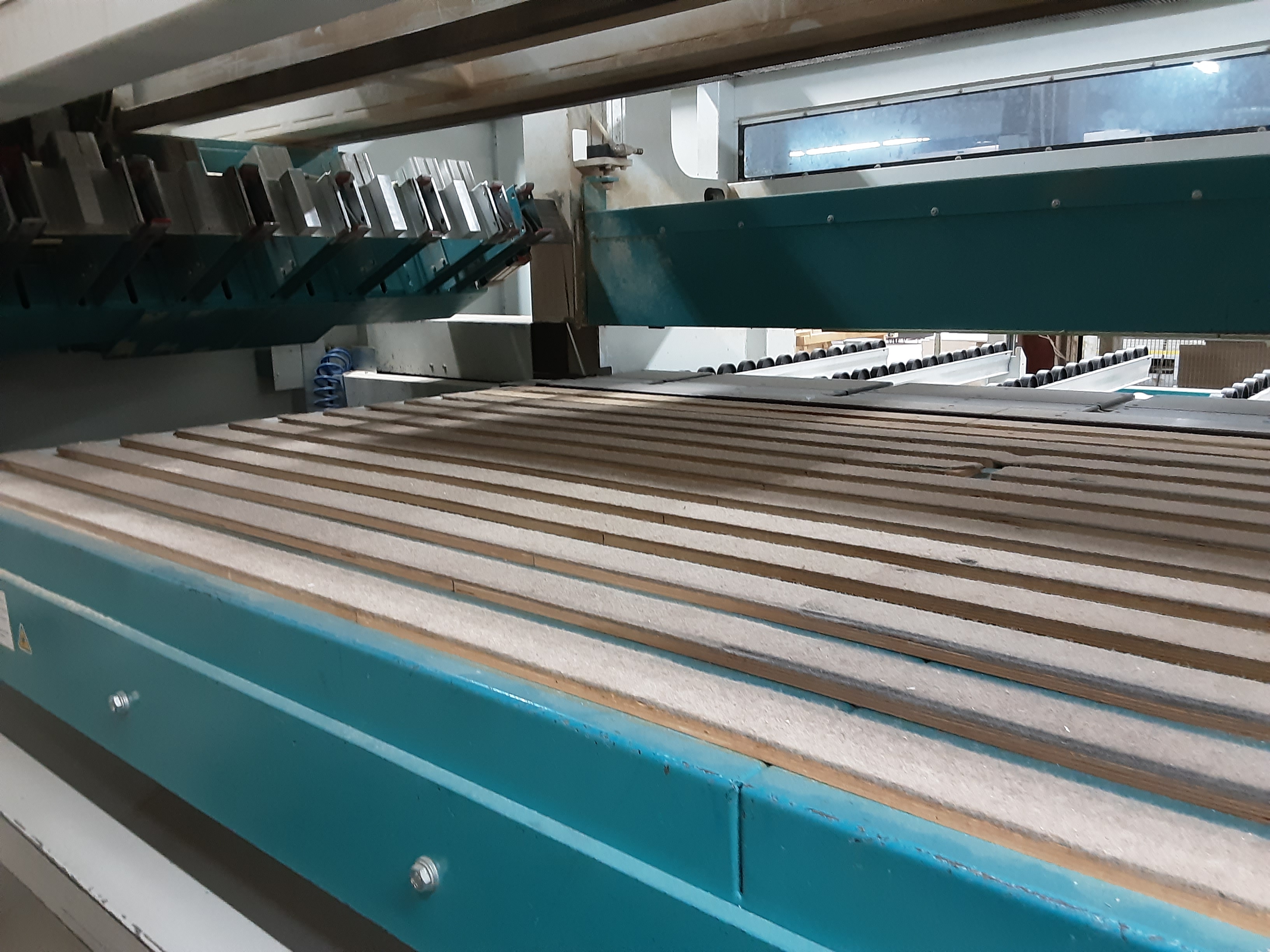
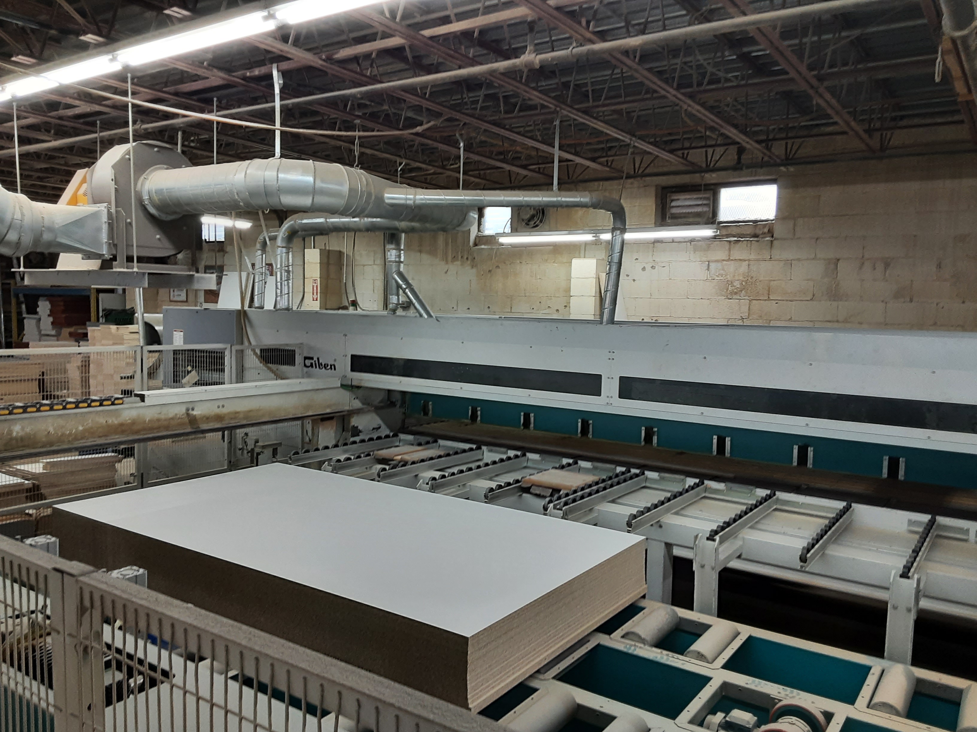
| Machine Capacities: | A UNIQUE ADVANTAGE FOR YOUR FACTORY is represented by the synthesis between high productivity and low occupied space. THE INLINE SQUARE FENCE with the longitudinal saw, permits a considerable reduction in execution time of the cutting cycle. TOTAL EFFECT, an angular system, producing greater productivity for its� type due its� COMPACT size and every movement is OPTIMISED. EASY TO OPERATE, operator has not to handle heavy stacks of panels, he simply directs them to the unloading after the cutting operation. HIGH VELOCITY of the saw carriage return and the pushers permit the NEW Angular cutting Centre extremely high productivity. THE CONTROL SYSTEM GDRIVEAXS BASIC guarantees the interface (OPTION) with the optimisation system GIBEN OPTIWINTM, label printing and other information necessary to formulate the working system justified for the cutting centre. PRODUCED IN ITALY and delivered to customers worldwide ICON 2 is the synthesis of 40 years experience. CONFIGURATION OF THE NEW ANGULAR CUTTING CENTER TECNICAL FEATURES -Length cutting machine: 4400 mm -Cross cutting machine: 1525 mm -Lift table dimension: 4400x1600 mm -Working height: 1050 mm -Control system: G-DRIVEAXS BASIC -Left handed -Loading method on lift table: From side conveyor -Max. opening of grippers: 110 mm -Blade projection: 105 mm -Main motor power: 18 Hp 13.2 kW (60 Hz) -Main blade diameter: 380 mm -Scoring blade diameter: 180 mm -Forward speed of saw carriage: 5 to 100 m/min. -Forward speed of pushers: 1 to 40 m/min -Return speed of pushers: 60 m/min -No. of grippers for length pusher: Five (5) -No. of grippers for cross pusher: Eight (8) -Evacuation of length trims: Moving table opening horizontal -Minimum book height: 10 mm -Minimum thickness for loading: 10 mm -Minimum board dimension for loading: 2440x1220 mm -Maximum board dimension for loading: 4200x1600 mm -Front aligners in length area: No. 3 -Side aligners in cross area: No. 2 bottom -Side aligners on pressure beam: No. 2 -Voltage: 600/60 Hz (by transformer) 1. Lifting Table CONSENTING A PERFECT PLANE during lifting and descending movements with loads not centralised on the table, thanks to the four corner syncronised reciprocal screw system, which others with alternative hydraulic or steel cable systems cannot guarantee. ZERO POINT of the stack is at the extreme left of the lifting table, which means the minimum time is required to move the cut strips from the longitudinal saw to the cross saw. FURTHERMORE, the optimisation of the saw carriage movement means the length of the saw carriage travel is minimised to that necessary to achieve a cut without wasted overtravel, contributing to a faster cutting cycle. MOREOVER, the use of the zero point in relation to the saw carriage travel OPTIMISES the dust extaction and eliminates the risk of dust and debris contaminating the machine area. IN ADDITION, the use of the zero point method is, for the fork lift operator a further advantage. No matter the length of the boards the loading point is always against a zero point thereby eliminating errors caused by miss alignment of the stack. AUTOMATIC COUNTING via encoder guarantees the lifting stroke of the table and quality of the loading cycle. The lift table is equipped with idle and 2 powered modules arranged for side loading. -Lift table dimension: 4400x1600 mm -Lift table stroke: 840 mm -Minimum thickness to book: 10 mm -Loading method: Side loading conveyor 3800 x 1600mm, equipped with 2 powered modules -Stack height without pit or raising machine: 680 mm -Stack height raising the machine 120 mm: 800 mm -Lift table rise and fall speed: 0,7 m/min -Lift table motor: 3 kW -Number of powered roller modules: 2 arranged for side loading 2. Support table of the book after loading is composed of unidirectional rollers supported in an aluminium profile 3. Front alignment with pneumatically operated squaring tools. 4. Moving table is positioned at its zero point in order to open an area for the evacuation of the length trims, both frontal and back. During sizing operations the moving table is closed to permit the transfer of strips to the cross machine. 5. Length and Cross pushers with robust steel guides, positioned perpendicular to the cutting lines and which supports the pusher carriage equipped with bilateral grippers. BRUSHLESS motors transmit via gearboxes and drive shafts to double pinions acting on precision rectified racks. This perfectly balanced mechanism assures high speeds, high precision and positioning accuracy. The position from the feedback loop from the motor and encoder via optical signal is guaranteed to be free from interference of dust, humidity and magnetism. THE LENGTH PUSHER grippers are equipped with retractable bottom appendixes (Giben patent), which allows the loading from the lift table to the support table by presenting a square face to the book and when the book is fully on the support table and after frontal alignment these bottom appendices lower to allow full clamping of the book. THE CROSS PUSHER equipped with fixed appendix grippers and rise and fall of the main element permits the pusher to return for the next strip(s) even if the table is occupied. -Forward speed of the pusher (cross pusher limited to 25 m/min according to �CE� norms): 1-40 m/min -Return speed of the pushers: 60 m/min -Brushless motor: Yes -Length pusher grippers: Five (5) -Cross pusher grippers: Eight (8) -Gripper opening: 110 mm 6. Length and cross saw machines. The steel machine bed structure is welded by gas metal arc, and then milled and refined by the CNC machines. The rigidity of the structure guarantees the optimal cut quality and high cutting speed, at the same time granting long life of the machine. -Length cutting machine: 4400 mm -Cross cutting machine: 1525 mm -Saw blade projection: 105 mm -Main motor power: 18 Hp 13,2 kW (60 Hz) -Scoring motor power: 2.5 Hp 1,8 kW (60 Hz) -Scoring saw regulation with a tool: External -Saw carriage motor: Brushless -Saw carriage forward speed: 5 to 100 m/min -Saw carriage return speed: 100 m/min THE BASE IS ESSENTIAL to guarantee a constant quality for the movement of the saw carriage and GIBEN is the unique company that has two bases positioned horizontally and cylindrical support guides parallel to the saw carriage travel. THE SPECIFIC DESIGN ATTRIBUTES OF THE STEEL MACHINE BED, the weights are distributed in the best possible manner, avoiding flexing and guaranteeing a perpendicular cut. MAXIMUM ACCESSIBILITY to main units of the saw. The saw carriage idle location is at outermost end position of the saw unit, assuring maximum ease of access. STEEL WORK BED with replaceable sections made from a synthetic material SINGLE PRESSURE BEAM. The beam produces an effect on both sides of the cut line giving first-rate clamping pressure on the book of panels. A TORSION BAR INSIDE the beam connects the two outermost ends, guaranteeing the perfect parallelism of the up and down motion of the beam. CLAMPING OF THE BOOK with full power of the beam including the last trim cut. Of particular merit are the apertures of the beam assuring the grippers release the book only after the beam has clamped the book. ALUMINIUM SAW CARRIAGE, the geometry of the construction puts the main blade at the tip of the ideal triangle, while the two outer guides are fixed at the two lower extremities of the ideal triangle (the saw bed). This is very different from other more economic construction types. The saw carriage does NOT allow blade deflection due to the two-sided support, in this way avoiding flexing of the structure from the effect of overhanging motors. This construction concept has been used by Giben in every model over the last 30 years and guarantees the maximum structural rigidity and stability during the cut cycle. THE SAW CARRIAGE TRAVEL IS CHAIN DRIVEN. This system (used also on the larger Giben saws and systems) allows the installation of motor and gearbox outside the machine bed, not on the saw carriage itself. This reduces the free weight of the saw carriage and guarantees the vibration free stroke, at the same time it is easily maintained with the minimum of knowledge and the chain can be obtained virtually anywhere in the world. THE SCORING BLADE, travelling in the front of the main blade, guarantees a chip free bottom cut. ONCE THE CUT IS CONCLUDED, the saw carriage returns with the blade below the working table, and prepares for the next cut. AUTOMATIC SAW TRAVEL CONTROL of the saw carriage relative to the primary material length or width. PNEUMATIC QUICK TOOLS RELEASE for the main blade and for the scoring blade. Blade change is easy on both the main and the scoring saws. The flanges that secure the blades in place are mechanically locked and pneumatically released. The entire process of changing blades is effortless and takes only a matter of seconds, due to the great accessibility of the saw carriage and the simplicity of the blade flanges. An added benefit is that no tools are required for the changing of blades. ADJUSTMENT OF THE SCORING BLADE is achieved, both horizontally and vertically, while the blades are running avoiding the need of opening the saw cover, which means that it is not necessary to stop the blades and the trial cuts can be executed immediately. DUST EXTRACTION is tremendously efficient; one lower connection point at floor level and two upper connection points on the pressure beam. 7. Pneumatic side aligner with two rollers. Two Side aligners move down automatically and align the book against the square fence with two full height 55mm diameter rollers. The downward motion is diagonal and does not contact the material until fully down. When the cut cycle nears its end, the side aligner moves away and up automatically in a manner not to scratch the material edges. Two further side aligners act on the strips during the advance of the pusher towards the front aligner and move away as the pusher approaches. 8. Front alignment of the book of strips occurs before the grippers close. This guarantees the dynamic alignment of the strips frontally and from the side and further guarantees the position of the strips relative to the cutting line. Once the alignment cycle has been achieved the aligner moves away from the strips. 9. Unloading area is composed of; -Square fence -Two air flotation tables 1300 x 510 mm. -One melamine covered table 500x500 mm movable, positioned between the two air flotation tables -One air generator for tables. 10. The control system GIBEN G-DRIVEAXS BASIC for programming the cutting schemes and control of the system comprises of an embedded PC over windows XP embedded operating system, Video and axis card. This system is unique in that the double control of the anti collision system permits high speed simultaneous optimised movements without the risk of damage. 11. Safety devices The machine described in this offer is constructed based upon the European standard �CE�. Any other special request for adapting the machine to any local/regional/national norm is at purchaser�s costs. 12. General technical features This equipment is manufactured by Giben International S.p.A., company with quality system certified ISO 9001. Please note: - The cutting quality depends on material to be cut and its physical properties, parallelism of each board and its finishing (surface). Furthermore, good quality tools are to be fitted; their condition and sharpening state may greatly affect the cutting quality. The cutting speed and the book height depend on the nature of boards to be cut and expected cutting quality. - The pusher positioning accuracy is +- 0,2 mm. - the minimum width of the strip is 100mm - the minimum width of a group of strips for a staggered cutting pattern cycle is 200mm - the minimum width of the strip near to the cross fence is 140 mm - the minimum width of the strip near to the cross fence to work in SP logic (front loading ) is 240 mm - The machine tables have been conceived so that to limit as much as possible any scratching on the surface of the board direct laying onto the working table. - The pile of material to be moved to the loading lift table must be flat and perpendicular in the two dimensions. - The boards and/or the piles of material shall not have overhanging or swollen edges - Boards and Piles the system has been designed with normal merchantable boards being the primary purpose of production. The pile entering the system must be presented with good alignment of the stack and at the zero point. |
| Sales Price: | CALL FOR PRICING |
| Contacts WW Machinery, Inc. sells pre-owned machinery on a first come, first served basis. Pre-owned machinery is not covered under any warranty or Government requirements. It is purchased "as-is - where-is, with all faults." Descriptions and specifications are to the best of our knowledge (some information is communicated via third party sources). It is strongly recommended that the machinery be inspected prior to purchasing to confirm the condition and specification. Additional charges such as crating and loading may apply. |